Tools:
The Designer (JNGBCDesign)
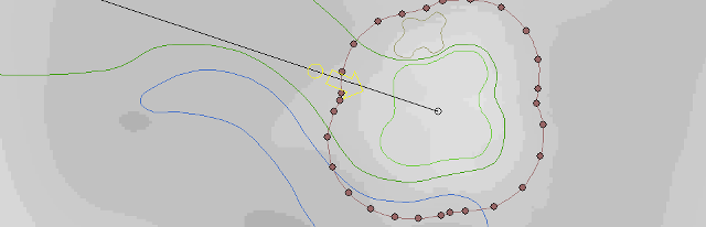
If you don't want cyber-golfers to curse your name, then you must insure your tee boxes are absolutely flat. This is my recommended procedure for doing that. Make a copy of the tee shape, Change Shape Type to terrain, and Stretch it by 10 to 15 feet. When changing shape types I prefer the terrain shape as it has the highest priority and so will always be on top of whatever shape it is residing on. Drag the new terrain shape over the tee as illustrated in the first figure below.
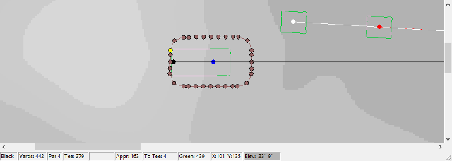
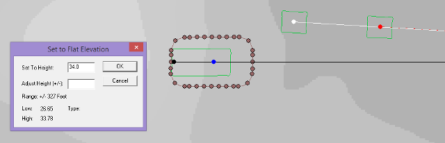
You will notice in the image above that one of the vertices is lit. I have identified that point on the terrain shape as having the greatest elevation (33' 9"). I am going to flatten the area covered by the terrain shape to roughly that value. Holding the shift key down I click on the Flatten to Highest icon, and enter the absolute value of 34.0 feet in the Set To Height input box and then click OK.
Flattening / Raising any area in such a manner often produces sharp changes in elevation. What we want to do now is smooth this area without drastically changing the flatness of the tee box. This is the reason for expanding the terrain shape in the first step above. The next step is to stretch the terrain shape again another 10 to 15 feet to cover a larger area for the smooth operations as illustrated in the figure below. With the expanded terrain shape selected, I will now click on the Smooth icon x number of times until I am satisfied with the result.
In many cases the area covered by the tee box will no longer be absolutely flat as a result of the smooth operations. To correct this I make another copy of the tee shape, change it to terrain, shrink it by about 2 feet, and position it over the tee shape as shown in the figure below. Then I move the cursor over the interior of the tee shape to determine a common elevation with which I will use to flatten the area beneath the terrain shape, using the same procedure in the second paragraph above. The animation below right details the step by step operations taken and documented above.

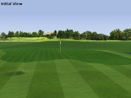
We now turn our attention to the green on this example hole. I have already decided upon a three fold series of terrain operations which I give the following terminology: Canting, undulating, and elevating. Canting refers to actions which result in a slanted surface. Undulating and elevating should be fairly well understood. My objective is to create a green with four or five different zones or target regions. If the cyber-golfer plans and executes a good approach shot they will be rewarded. otherwise they may have to settle for par at best.
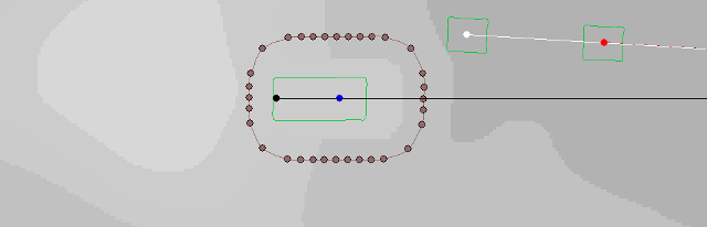
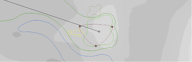
The canting procedure begins by creating a new 3-point triangular terrain shape as shown in the figure below. I shall use this shape to adjust the overall incline of the green to slope from back to front and left to right relative to the current view as shown by the position of the view arrow.
With the terrain shape in the first position (pictured below), I click on the Slope Left icon while watching the rendered view for the desired result. If necessary, I will repeat this action, otherwise I will move the shape to the second position to affect the back left side of the green.
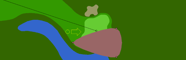
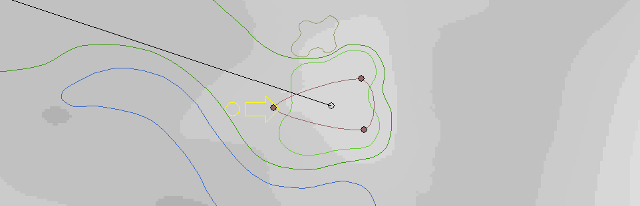
The neat thing about this simple three-point triangular terrain shape is the ease with which it is to reshape, resize, and rotate. This I have done as you can see in the figure below. I am now ready to adjust the general inclination, or slope of the green from left to right. Beginning with the position of the shape near the center of the green, I click on the Slope forward icon which enhances the slope from the top of the design window towards the bottom. After each action I move the shape toward the left edge of the green near the bunker and repeat the sloping action.
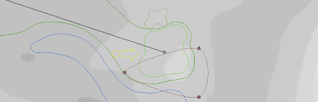
Lastly, I want to create a slight ridge down the middle of the green. Depending on the pin placement, this will give cause to the cyber-golfer to hit an accurate approach shot to find the correct side of the green. As you can see, I have adjusted the shape and direction of the terrain shape again, positioned it to have the necessary effect, and clicked once on the Bulge up icon. The animation below right illustrates the canting operations documented in this section.
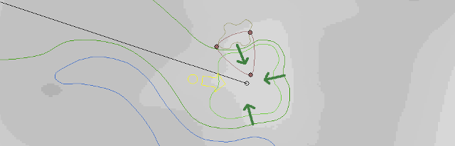
To add undulations onto the green surface I'll use the same three-point terrain shape, resized as needed. I will then position and align this shape as indicated by the green arrows in the figure below. At each position I click just one time on the Bulge up icon. You can watch the action in the animated image below right. You should begin to identify those target zones I mentioned earlier.
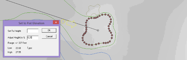
And here we are, the last stage in greens construction. I don't pretend to be even a fair golfer IRL but I do confess to enjoying the trip around a golf course more than my playing ability. One thing I noticed is how course architects build greens. Among other things, they are elevated and sloped in such a manner as to shed water. To do the same thing for our cyber golf course I make a copy of the green shape, change it to terrain (because of its priority), and position it precisely over the green as shown in the figure below.
With the terrain shape now selected and positioned correctly, I will hold the Shift key down and click on any of the Flatten or Raise tool icons. In the dialog window that pops up I enter a value of 0.25 feet in the Adjust Height input box. Next, stretch / expand the terrain shape by five feet and repeat the height adjustment. I repeat this procedure four times to produce the desired effect.
Lastly, I expand the terrain shape by approximately 15 to 20 feet so that it covers the entire affected area and click the Smooth icon x number of times until I'm happy with the result. The animation below right shows step by step the elevation technique I used.